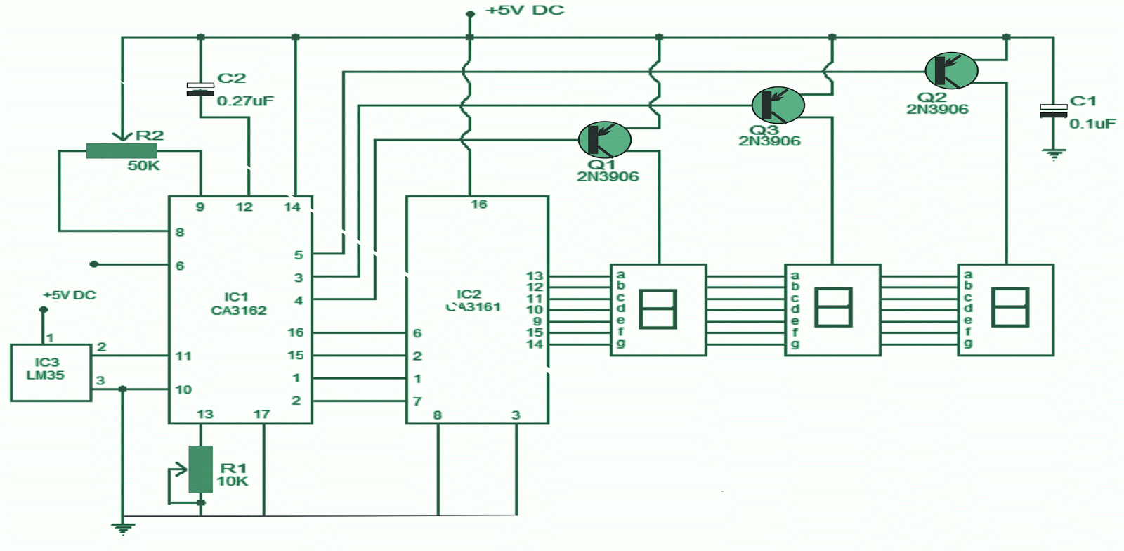
Making an electronic thermometer circuit may be understood in the following post. Here IC LM35 is utilized for sensing the temperature ranges. A voltage proportional to the temperature shall be obtainable at pin 2 of the LM35 and this voltage is associated to the high input pin (pin11) of the CA3162. CA3162 does the work of transforming this analogue voltage in to a BCD form. POT R1 attached at pin 13 of the CA3162 is utilized for gain adjustment while POT R2 may be used for ZERO alignment. Capacitor C2 is the adding capacitor of the A/D converter circuitry inside the IC. The functioning of the CA3162 is as accompanies, the voltage put on the input pin (pin11) is converted into a current (by means of the integrated V/I converter circuit) that charges the tying up capacitor C2 for a preset measure of them. Subsequently the integrating is shut off from the V/I converter circuit including a reference steady current source is connected to the integrating capacitor. The time taken for the charge to bring back to its actual value is pointed out and the quantity of clock cycles expired in this particular time will be indicative of the charge characterized by the input voltage (voltage applied to pin 11). The point of recovery is detected utilizing an interior comparator which latches the counter and the count is therefore multiplexed into the BCD outputs and the whole sequence is prolonged. The hold pin CA3162 (pin6) can be utilized for operating the IC in several techniques. When the hold pin is grounded or allowed to remain open the IC carries on in low speed mode (sampling rate is 4Hz). When hold pin is held at +5V, the IC functions in high speed mode i.e. a sampling rate of 96Hz. When the hold pin is clutched at a fixed 1.2V, the BCD output latches to the current level. C1 is the power supply bypass capacitor whose job could be to forego noise if almost any from the power source line.
Circuit Diagram :
The upcoming portion of the circuit is the BCD to seven segment decoder and also display driver section. For that intention CA3161 is commonly employed. The BCD output pins of the CA3162 are hooked up to the input pins of the CA3161. Transistors Q1, Q2, Q3 common anode terminals of the in accordance seven segments displays. Q1, Q2, Q3 are influenced by the 4, 3, 5 pins (digit driver pins) of the CA3162 respectively.
The electronic thermometer circuit is generally put together on a vero board or on a PCB.
Use 5V DC for powering the circuit.
POT R2 can be utilized for Zero realignment.
IC2 and IC1 needs to be mounted on holders.
Capacitor C1 needs to be placed as up close as you possibly can to the power and ground pins of the CA3162.
Capacitor C2 could be a polyester type whereas C1 could be a ceramic capacitor.
The DC power source used for powering this circuit should be well regulated and exempt from any sort of noise.
The type numbers of the driver transistor are not essential you can also make appropriate substitutions.
Hold function can be enabled by supplying the pin 6 with 1.2V employing a voltage divider network.
Notes.
The electronic thermometer circuit is generally put together on a vero board or on a PCB.
Use 5V DC for powering the circuit.
POT R2 can be utilized for Zero realignment.
IC2 and IC1 needs to be mounted on holders.
Capacitor C1 needs to be placed as up close as you possibly can to the power and ground pins of the CA3162.
Capacitor C2 could be a polyester type whereas C1 could be a ceramic capacitor.
The DC power source used for powering this circuit should be well regulated and exempt from any sort of noise.
The type numbers of the driver transistor are not essential you can also make appropriate substitutions.
Hold function can be enabled by supplying the pin 6 with 1.2V employing a voltage divider network.


0 comments:
Post a Comment